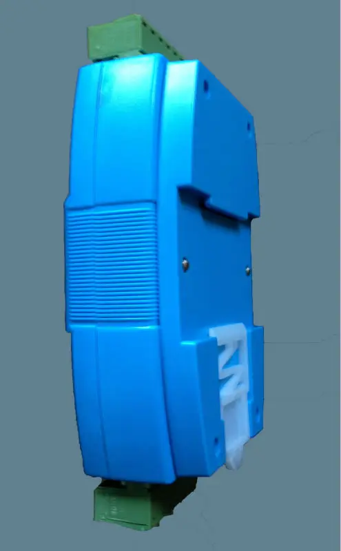
WP8026ADAM ( 16DI ) _ Digital enter module / Optocoupler remoted / RS485 MODBUS RTU communications
$27.00

1.We offer module instruction guide and debugging software program, please go to the next URL website for obtain.
https://www.shwellpro.com/obtain
2.When you’ve got any downside of our merchandise, please contact us through order message or electronic mail, we are going to enable you to unravel the issue.
3.If customized tax wanted,purchaser must bear the associated fee,vendor doesn’t bear any customized tax.
4.Any downside simply contact us through order message or electronic mail befor dispute and unfavourable suggestions.Your suport is essential to us,thanks on your type understanding!

Merchandise Particulars
1、Product description
- Sixteen optoelectronic isolation digital enter channel (Low stage enter)
- RS485 MODBUS RTU normal communication protocol
- Netted with configuration software program, PLC or trade contact panel
- Communication, digital enter and digital output standing LED
- Communication circuit designed for thunder safety and interference immunity
- Used for sign assortment and management in industrial area
2、Specification
- Digital enter channel 16ch (Low stage enter)
- Working temperature -20~70℃
- Exterior energy provide DC9V~30V/2W
- Isolation safety DC1500V
- Set up methodology Normal DIN slide rail or screw
- Dimension 125×73×35mm
3、Interface description
|
AVcc |
Exterior energy provide enter constructive |
|
AGnd |
Exterior energy provide enter unfavourable / Energy floor |
|
DI_01 |
Digital enter channel 1 |
|
DI_02 |
Digital enter channel 2 |
|
DI_03 |
Digital enter channel 3 |
|
DI_04 |
Digital enter channel 4 |
|
DI_05 |
Digital enter channel 5 |
|
DI_06 |
Digital enter channel 6 |
|
DI_07 |
Digital enter channel 7 |
|
DI_08 |
Digital enter channel 8 |
|
DI_09 |
Digital enter channel 9 |
|
DI_10 |
Digital enter channel 10 |
|
DI_11 |
Digital enter channel 11 |
|
DI_12 |
Digital enter channel 12 |
|
DI_13 |
Digital enter channel 13 |
|
DI_14 |
Digital enter channel 14 |
|
DI_15 |
Digital enter channel 15 |
|
DI_16 |
Digital enter channel 16 |
|
485B |
RS485 sign B- |
|
485A |
RS485 sign A+ |
4、Digital enter software diagram

5、Communication description
5.1、Communication parameter: 9600, None, 8, 1 (default setting)
|
Parameter |
Description |
|
9600 |
baud charge |
|
None |
verify bit |
|
8 |
information bit |
|
1 |
cease bit |
5.2、Command for digital enter information studying
Ship: 01 02 00 00 00 10 79 C6 (instance/hex)
|
information |
byte |
information description |
comment |
|
01 |
1 |
module deal with |
deal with vary:01-FE |
|
02 |
1 |
operate code |
02-read digital enter register |
|
0000 |
2 |
register deal with (1X sort) |
0000-starting register deal with |
|
0010 |
2 |
register quantity |
0010-read 16 registers |
|
79C6 |
2 |
CRC verify code |
CRC verify code for all information |
Obtain: 01 02 02 21 A0 A1 90 (instance/hex)
|
information |
byte |
information description |
comment |
|
01 |
1 |
module deal with |
deal with vary:01-FE |
|
02 |
1 |
operate code |
02-read digital enter register |
|
02 |
1 |
byte of information |
02-read 2 bytes |
|
21A0 |
2 |
learn information |
21A0-digital enter information |
|
A190 |
2 |
CRC verify code |
CRC verify code for all information |
This command reads module’s digital enter information.
The information of the digital enter is “21”, will probably be “00100001” after changing to binary information. The eight bits of information correspond to DI_08~DI_01. It means DI_06 and DI_01 are ON.
The information of the digital enter is “A0”, will probably be “10100000” after changing to binary information. The eight bits of information correspond to DI_16~DI_09. It means DI_16 and DI_14 are ON.
5.3、Command for module deal with setting
Ship:00 06 00 64 00 01 08 04 (instance/hex)
|
date |
byte |
information description |
comment |
|
00 |
1 |
module deal with |
00-broadcast deal with |
|
06 |
1 |
operate code |
06-write single holding register |
|
0064 |
2 |
register deal with (4X sort) |
0064-module deal with register |
|
0001 |
2 |
write information |
0001- module deal with, vary:0001-00FE |
|
0804 |
2 |
CRC verify code |
CRC verify code for all information |
Obtain:00 06 00 64 00 01 08 04 (instance/hex)
This command units module deal with (slave deal with) as “01” (default setting). This setting may very well be saved when energy off. This can be a broadcast command. It wants to make sure that just one module is linked to the grasp.
When module receives right command, it’s going to ship response again to the grasp.
5.4、Command for communication parameter setting
Ship:01 06 00 65 00 02 18 14 (instance/hex)
|
information |
byte |
information description |
comment |
|
01 |
1 |
module deal with |
deal with vary:01-FE |
|
06 |
1 |
operate code |
06-write single holding register |
|
0065 |
2 |
register deal with (4X sort) |
0065-communication parameter register |
|
0002 |
2 |
write information |
0001- 4800, None, 8, 1 0002- 9600, None, 8, 1 0003- 19200, None, 8, 1 0004- 38400, None, 8, 1 0005- 4800, Even, 8, 1 0006- 9600, Even, 8, 1 0007- 19200, Even, 8, 1 0008- 38400, Even, 8, 1 |
|
1814 |
2 |
CRC verify code |
CRC verify code for all information |
Obtain:01 06 00 65 00 02 18 14 (instance/hex)
This command units communication parameter as “9600, None, 8, 1” (default setting). This setting may very well be saved when energy off.
When module receives right command, it’s going to ship response again to the grasp.
6、POWER/DATA LED description
- When module powered on, LED is inexperienced.
- When module is below communication, LED is twinkling.
- When module receives right command, LED is inexperienced.
- When module receives incorrect command or different module’s command, LED is purple.
7、PC debugging description
We offer a debugging software program for operate testing and parameter setting. Please observe the steps beneath:
- Join pc to module with RS485 converter.
- Join DC12V or DC24V energy to module and energy on. To keep away from any pointless injury, please be certain that the ability constructive and unfavourable terminals are accurately linked earlier than energy on.
- Open the software program and choose the mannequin of module, you will note the window of operate testing or parameter setting.
- Set communication parameter and open the serial port.
- Choose corresponding setting and click on “Learn” or “Write” button.

8、RS485 community diagram

Specification: WP8026ADAM ( 16DI ) _ Digital enter module / Optocoupler remoted / RS485 MODBUS RTU communications
|
User Reviews
Be the first to review “WP8026ADAM ( 16DI ) _ Digital enter module / Optocoupler remoted / RS485 MODBUS RTU communications”
You must be logged in to post a review.







There are no reviews yet.